Brake controllers are an essential component of any towing setup, and wiring them correctly is crucial for safe and reliable operation. In this guide, we will walk you through the process of wiring a universal pigtail brake controller, covering the key concepts, tools, and steps involved.
Understanding Brake Controller Wiring
Before we dive into the wiring process, it's essential to understand the basics of brake controller wiring. A brake controller is an electronic device that regulates the flow of electrical current to the trailer's brakes. It is typically connected to the tow vehicle's electrical system and the trailer's brake wiring.
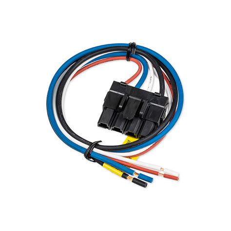
The universal pigtail brake controller wiring harness is a pre-assembled wiring harness that connects the brake controller to the tow vehicle's electrical system. It usually consists of a set of wires with pre-crimped connectors that match the brake controller's terminals.
Tools and Materials Needed
To wire a universal pigtail brake controller, you will need the following tools and materials:
- Universal pigtail brake controller wiring harness
- Brake controller
- Tow vehicle's electrical system wiring diagram
- Wire strippers
- Wire connectors
- Electrical tape
- Multimeter (optional)
Step 1: Identify the Brake Controller's Terminals
The first step in wiring a universal pigtail brake controller is to identify the brake controller's terminals. The terminals are usually labeled as follows:
- B (Battery)
- B- (Battery Negative)
- P (Power)
- B/O (Brake Output)
- I (Input)
Consult your brake controller's manual or wiring diagram to confirm the terminal labels.
Step 2: Connect the Wiring Harness to the Brake Controller
Next, connect the universal pigtail wiring harness to the brake controller's terminals. Match the wire colors and connectors to the terminal labels. Typically:
- Red wire to B (Battery) terminal
- Black wire to B- (Battery Negative) terminal
- Yellow wire to P (Power) terminal
- Blue wire to B/O (Brake Output) terminal
- White wire to I (Input) terminal
Use wire connectors to secure the connections.
Step 3: Connect the Wiring Harness to the Tow Vehicle's Electrical System
Now, connect the wiring harness to the tow vehicle's electrical system. Consult your tow vehicle's wiring diagram to locate the corresponding wires:
- Battery wire (usually red or yellow)
- Brake light wire (usually yellow or green)
- Turn signal wires (usually yellow or green)
- Ground wire (usually black or brown)
Connect the wiring harness to the corresponding wires using wire connectors.
Step 4: Connect the Wiring Harness to the Trailer's Brake Wiring
Finally, connect the wiring harness to the trailer's brake wiring. Consult your trailer's wiring diagram to locate the corresponding wires:
- Brake wire (usually blue or red)
- Turn signal wires (usually yellow or green)
Connect the wiring harness to the corresponding wires using wire connectors.
Testing the Brake Controller
Once the wiring is complete, test the brake controller to ensure it is functioning correctly. Use a multimeter to check the voltage and current output. Consult your brake controller's manual for specific testing procedures.
Gallery of Universal Pigtail Brake Controller Wiring Harness


FAQs
What is a universal pigtail brake controller wiring harness?
+A universal pigtail brake controller wiring harness is a pre-assembled wiring harness that connects the brake controller to the tow vehicle's electrical system.
How do I identify the brake controller's terminals?
+Consult your brake controller's manual or wiring diagram to confirm the terminal labels.
How do I test the brake controller?
+Use a multimeter to check the voltage and current output. Consult your brake controller's manual for specific testing procedures.
By following these steps and using the provided wiring diagram, you should be able to successfully wire a universal pigtail brake controller. Remember to test the brake controller to ensure it is functioning correctly. If you have any further questions or concerns, please don't hesitate to reach out.
